VD-Link Telemetry / Video Setup
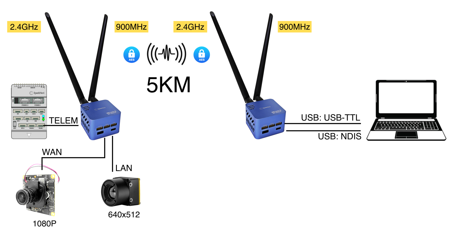
The SparkNavi VD-Link-S is a dual-band (2.4 GHz + 900 MHz) long-range wireless datalink based on Microhard radio modules. With an effective range of 5 km, it can simultaneously transmit:
- Telemetry data (MAVLink, from the SparkNavi Blue flight controller)
- Visible-light IP camera video (via WAN port)
- Thermal / IR camera video (via LAN port)
This guide covers the full flow: wiring, Microhard configuration, video streaming, and TX Power tuning.

⚠️ Critical Safety Warning (Read First)
Wrong cable connection will permanently damage the flight controller
The VD-Link TELEM, WAN, and LAN ports all provide voltage output, and all three use the same GH1.25 connector.
NEVER connect a WAN or LAN cable to the flight controller's TELEM1 / TELEM2 port — doing so will permanently damage the flight controller.
Verify the port label and pinout before every connection. Only the TELEM connector is intended for the SparkNavi Blue TELEM1.
System Architecture
VD-Link uses a Sky-side (aircraft) + Ground-side (GCS) two-module design with AES encryption on all signals:
| Component | Aircraft side | Ground side |
|---|---|---|
| Flight controller | SparkNavi Blue → TELEM | — |
| 1080P IP camera | → WAN | — |
| 640×512 thermal camera | → LAN | — |
| GCS PC | — | USB-TTL (telemetry) / USB-NDIS (video) |
Hardware Port Layout
Bottom face of the VD-Link module:
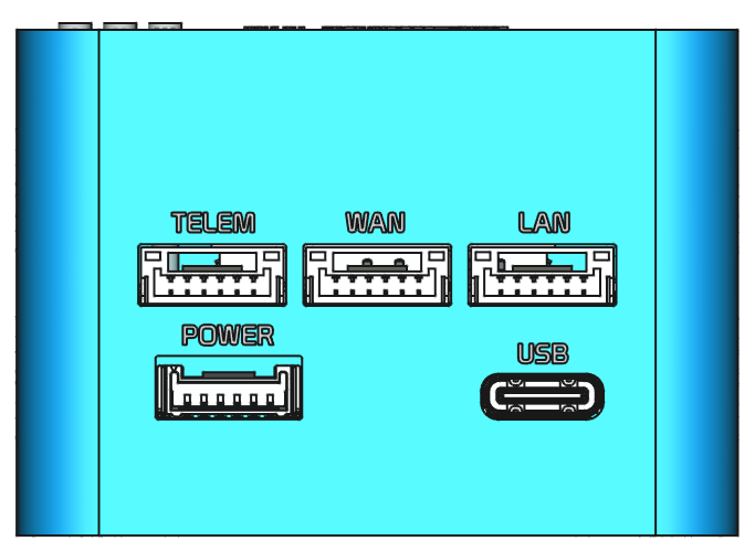
| Port | Purpose | Connector |
|---|---|---|
| TELEM | FC telemetry (to SparkNavi Blue) | GH1.25 6-pin |
| WAN | IP camera (visible) — RTSP stream | GH1.25 6-pin, +12V output |
| LAN | Thermal / secondary video — RTSP stream | GH1.25 6-pin, +12V output |
| POWER | Power input (max +55V / 12S) | GH1.25 |
| USB | Ground PC USB Type-C (NDIS network + USB-TTL telemetry) | USB-C |
Antenna Assignment
| Antenna port | Band |
|---|---|
| ANT1 | 2.4 GHz |
| ANT2 | 900 MHz |
The dual-band design avoids single-band interference; if one band fails, the link automatically falls back to the other.
Complete Wiring Diagram
Typical aircraft-side wiring: SparkNavi Blue + visible IP camera + thermal camera

Pin definitions for each GH1.25 connector:
| Pin | TELEM | WAN | LAN | POWER |
|---|---|---|---|---|
| 1 | +5V | +12V | +12V | BAT+ |
| 2 | RX (Input) | TX+ | TX+ | BAT+ |
| 3 | TX (Output) | TX- | TX- | BAT+ |
| 4 | × | RX+ | RX+ | GND |
| 5 | × | RX- | RX- | GND |
| 6 | GND | GND | GND | GND |
⚠️ Reminder: Pin 1 of WAN / LAN is +12V output (camera power). If miswired to FC TELEM, that 12V hits the flight controller's 5V logic circuitry directly.
Web Admin Login
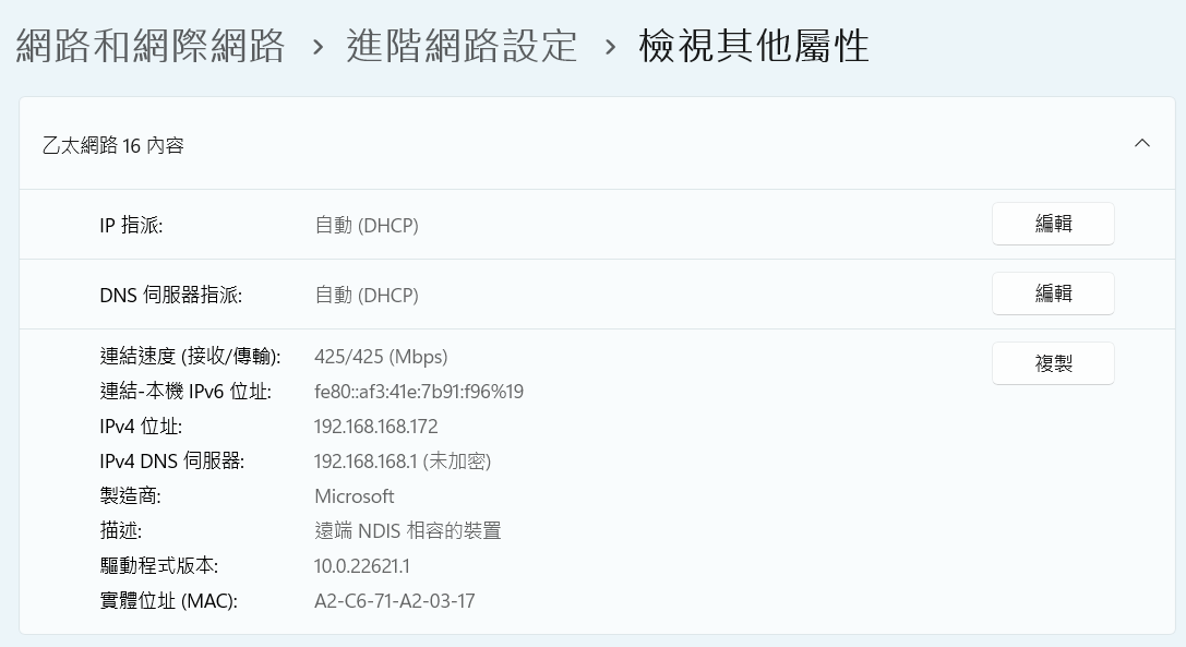
When the ground-side VD-Link is connected via USB Type-C, Windows automatically detects it as a Remote NDIS Compatible Device and obtains an IP automatically (typically in the 192.168.168.x range).
NDIS link speed is up to 425 Mbps, sufficient for dual high-resolution video streams:
Open a browser and access the Microhard web UI:
| Item | Default value |
|---|---|
| URL | http://192.168.168.1 (refer to label on bottom of unit) |
| Username | admin |
| Password | sparknavi |
Change the default password immediately after first login
The default password is publicly documented. Before any production deployment, go to Admin → Change Password and set a strong password, otherwise anyone on the same network segment can take over your link.
Microhard Master Configuration (Ground Side)
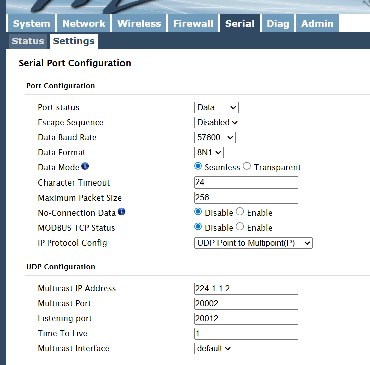
In the Microhard web UI → Serial → Settings:
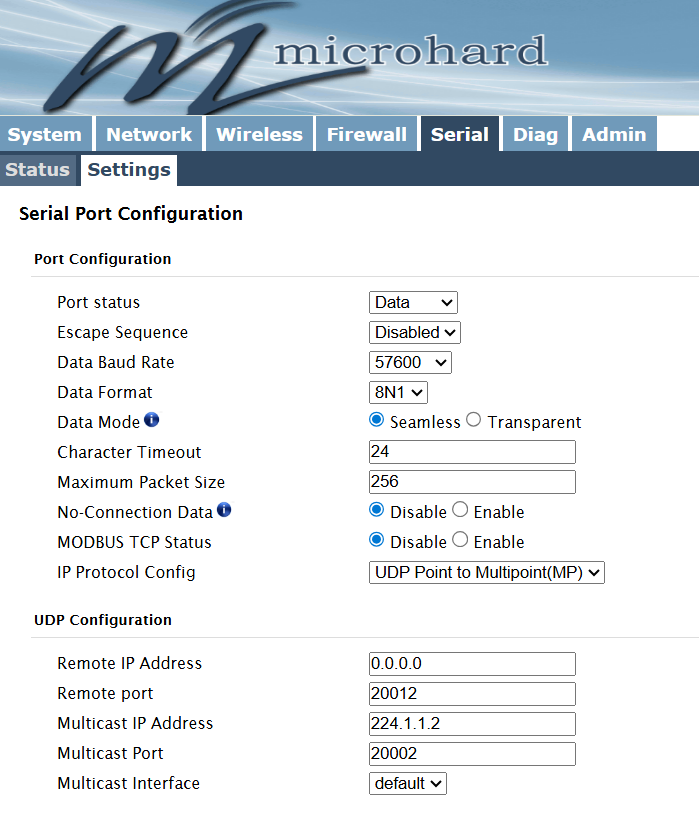
Port Configuration
| Field | Value |
|---|---|
| Port status | Data |
| Escape Sequence | Disabled |
| Data Baud Rate | 57600 |
| Data Format | 8N1 |
| Data Mode | Seamless |
| Character Timeout | 24 |
| Maximum Packet Size | 256 |
| No-Connection Data | Disable |
| MODBUS TCP Status | Disable |
| IP Protocol Config | UDP Point to Multipoint(MP) |
UDP Configuration
| Field | Value |
|---|---|
| Remote IP Address | 0.0.0.0 |
| Remote port | 20012 |
| Multicast IP Address | 224.1.1.2 |
| Multicast Port | 20002 |
| Multicast Interface | default |
Microhard Slave Configuration (Aircraft Side)
In the Slave-side Microhard web UI → Serial → Settings:
Port Configuration
Same as Master (Data Baud Rate = 57600, IP Protocol = UDP Point to Multipoint).
UDP Configuration
| Field | Value |
|---|---|
| Multicast IP Address | 224.1.1.2 |
| Multicast Port | 20002 |
| Listening port | 20012 |
| Time To Live | 1 |
| Multicast Interface | default |
⚠️ Key difference: the Slave has Listening port = 20012, matching the Master's Remote port = 20012.
TX Power Tuning (Important Operational Tip)
Bench testing vs flight testing — TX Power must differ
During bench testing (aircraft and ground modules placed within tens of centimeters to a few meters), if TX Power is too high, the radio enters saturation — the RX side is overwhelmed by the local TX, paradoxically losing signal.
Recommended TX Power settings:
| Scenario | Recommended TX Power |
|---|---|
| Desktop loop test (< 1 meter) | 10 dBm |
| Close-range function test (1–10 meters) | 15 dBm |
| Production / flight test (> 50 meters) | 30 dBm |
Configuration path: Microhard web UI → Wireless → RF → Tx Power:

Flight Controller Wiring (SparkNavi Blue)
Connect the Slave-side Microhard module's TELEM port to the SparkNavi Blue TELEM1 connector:
| Pin | Signal | SparkNavi Blue TELEM1 |
|---|---|---|
| 1 | +5V | +5V |
| 2 | TX (VD-Link → FC) | RX |
| 3 | RX (FC → VD-Link) | TX |
| 6 | GND | GND |
ArduPilot SERIAL1 (TELEM1) Parameters
| Parameter | Value | Description |
|---|---|---|
SERIAL1_PROTOCOL |
2 (MAVLink2) |
TELEM1 protocol |
SERIAL1_BAUD |
57 (57600) |
TELEM1 baud rate (matches Microhard) |
Ground-Side GCS Connection
Mission Planner Telemetry Link
Connection settings:
- Connection type: UDP
- Listen Port:
20002(matches the Multicast Port)
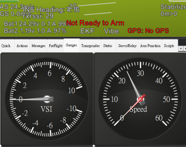
Click Connect — Mission Planner should receive MAVLink heartbeats from SparkNavi Blue.
The HUD should display flight data:
Video Streaming (RTSP)
The Sky-side IP camera (connected to the WAN port) streams over the NDIS network to the ground PC. Default RTSP URL:
rtsp://admin:admin@192.168.168.88/11
(IP varies by your IP camera configuration; the above is a typical example.)
Display Video Using GStreamer (Windows + NVIDIA GPU)
Three command variants for different scenarios. All support automatic reconnection after signal loss:
Option 1: Standard D3D11 (Windows DirectX, best compatibility)
gst-launch-1.0.exe rtspsrc location=rtsp://admin:admin@192.168.168.88/11 protocols=udp latency=0 drop-on-latency=true ! rtph264depay ! h264parse ! nvh264dec ! d3d11videosink sync=false async=false qos=false
Option 2: OpenGL output (slightly lower latency)
gst-launch-1.0.exe rtspsrc location=rtsp://admin:admin@192.168.168.88/11 protocols=udp latency=0 drop-on-latency=true ! rtph264depay ! h264parse ! nvh264dec ! glimagesink sync=false async=false qos=false
Option 3: CUDA direct-to-GL (lowest latency on NVIDIA cards)
gst-launch-1.0.exe rtspsrc location=rtsp://admin:admin@192.168.168.88/11 protocols=udp latency=0 drop-on-latency=true ! rtph264depay ! h264parse ! nvh264dec cuda-device-id=0 ! cudadownload ! glimagesink sync=false async=false qos=false
Requirements
- GStreamer 1.0+: official download
- Choose MSVC + Complete package during install
- Includes
nvh264dec(NVIDIA Video Codec SDK)
If you use an AMD or Intel iGPU, replace nvh264dec with:
- AMD: d3d11h264dec
- Intel QuickSync: mfh264dec
FAQ
Q: Mission Planner doesn't receive UDP packets?
A: Check:
1. Master and Slave Multicast IP / Port match
2. Firewall isn't blocking UDP port 20002
3. Slave Microhard is actually receiving serial data (check Serial Status in Microhard web UI)
4. SparkNavi Blue's SERIAL1_PROTOCOL = 2 and SERIAL1_BAUD = 57 are set correctly
Q: On bench, Mission Planner connection is intermittent?
A: That's TX Power saturation. Drop to 10–15 dBm — see the TX Power section above.
Q: NDIS device doesn't appear in Windows?
A: Check: 1. The USB Type-C cable supports data transfer (some USB-C cables are charge-only) 2. Device Manager → Network Adapters shows "Remote NDIS Compatible Device" 3. Try unplugging and waiting 10 seconds before reconnecting
Q: gst-launch shows a black screen?
A: Check:
1. RTSP IP / credentials are correct (camera default is usually admin:admin, NOT the Microhard admin:sparknavi)
2. Camera path /11 is the main stream; /12 is typically a sub-stream
3. Firewall isn't blocking UDP
Q: Why Multipoint instead of Point-to-Point?
A: In Multipoint mode, multiple ground GCS can simultaneously receive data from one aircraft (command center + operator + monitoring PC all connect at once).